1. Input
1. Input
Configure settings related to input of the scanner.
| RS-232C | The scanner can control command via RS-232C communication. It cannot be disabled. |
|---|---|
| Ethernet | The scanner can control command via Ethernet. It cannot be disabled. |
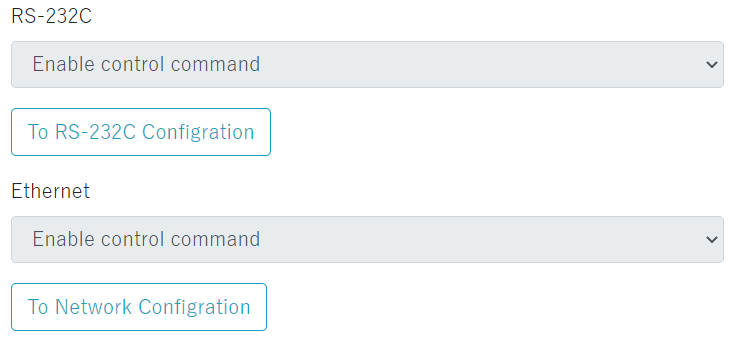
| To RS-232C configuration To Network configuration |
Click to jump to 3. Communication. * A warning will be displayed when jumping if there are changes in the settings. |
|---|
Input Terminal Configuration
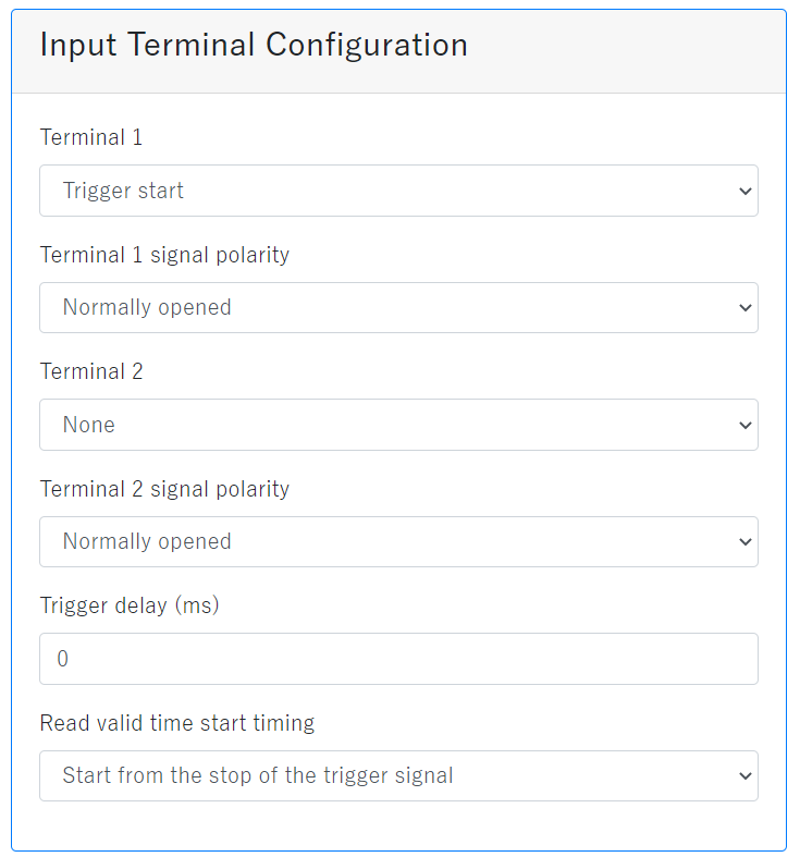
| Terminal 1 | Select the operation from "None" or "Trigger start" for the input terminal 1 function. |
|---|---|
| Terminal 1 signal polarity |
Normally open/close of the IN terminal 1 can be selected. Since the input circuit is an AC input photo coupler, it supports both NPN and PNP connections. Normally closed:Nomally Inputs source signal is closed. When active the signal is opened. Normally opened:Nomally Inputs source signal is opened. When active the signal is closed. Refer to the FA-5201 users manual for details. |
| Terminal 2 | Select the operation from "None" or "Trigger start" for the input terminal 2 function. |
| Terminal 2 signal polarity |
Normally open/close of the IN terminal 2 can be selected. Since the input circuit is an AC input photo coupler, it supports both NPN and PNP connections. Normally closed:Nomally Inputs source signal is closed. When active the signal is opened. Normally opened:Nomally Inputs source signal is opened. When active the signal is closed. Refer to the FA-5201 users manual for details. By default, trigger signal and read time are synchronized. As long as TRIGn signal is active, the scanner will read.(This figure shows that Nomally opened.)  |
| Trigger delay(ms) | The waiting time from when the scanner receives the trigger start command until the scanner actually starts reading. Set between 0 ms to 9999 ms. Set the trigger delay for each bank. |
| Read valid time start timing | Set the effective read time from "Start from the stop of the trigger signal" or "Start from the start of the trigger signal". Refer to the FA-5201 users manual for details. |