3.Communication
3. Communication
Configure settings related to the communication of the scanner
Network settings
Change the scanner's IP address, the TCP port and host name.
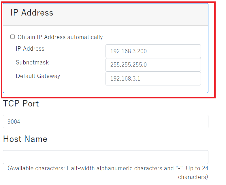
| Obtain IP address automatically | Check here to connect DHCP server and obtain the IP address of the scanner automatically, such as connecting the scanner to a router. |
|---|---|
| IP address | Enter the IP address of the scanner to use. Set the IP address that does not overlap with the IP address of other devices on the same network. |
| Subnetmask | Enter the subnetmask to use. Set according to the network to operate. |
| Default gateway | Enter the default gateway to use. Set according to the network to operate. |
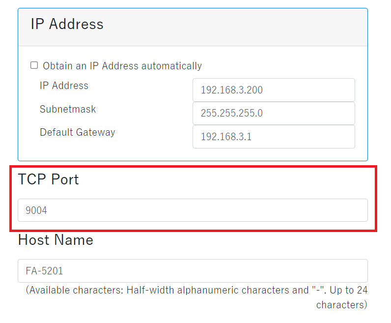
| TCP port | Enter the TCP port to use. Unless there is a special reason, use the default. *Following values cannot set to the TCP port.
※ If there is no communication, the FA-5201 sends a NUL character (0x00) every 60 seconds so that the connection does not occur.(Keep Alive)。 |
|---|
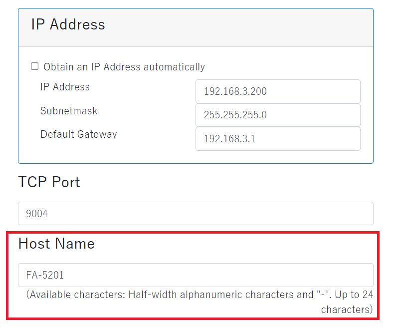
| Host name | Enter the host name to use. It can be changed according to the install location and role.
Following characters can be used for the host name.
|
|---|
Industrial protocol
Setting when connecting the scanner and PLC.
Corresponded PLC
MITSUBISHI ELECTRIC Corporation
| Series | Corresponded Protocol |
|---|---|
| MELSEC Q Series | MC Protocol(UDP) |
| MELSEC LQ Series | MC Protocol(UDP) |
| MELSEC iQ-R Series | MC Protocol(UDP) |
| MELSEC iQ-F Series | MC Protocol(UDP) |
Corresponded Protocol
- PLC Link
PLC link is a communication method that directly reads and writes data to the internal memory (data memory, data register) of PLC through Ethernet.- MC Protocol
FA-5201 is one of the PLC links and supports the MC protocol, which is the communication method of Mitsubishi Electric's PLC.The biography format is compatible with "3E frame".
- MC Protocol
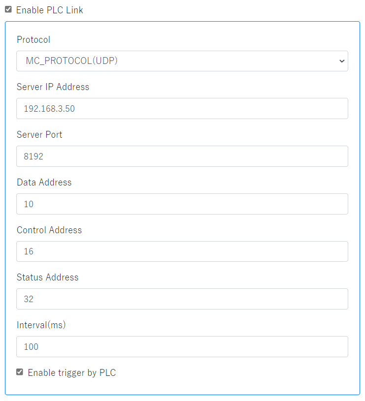
| Enable PLC Link | Check here to connect PLC and FA-5201. |
|---|---|
| Protocol | This can be selected only with the "MC_PROTOCOL(UDP)" used by Mitsubishi PLC. Currently, only UDP communication is supported. |
| Server address | Enter the PLC server address to use. |
| Server port | Enter the PLC server port to use. |
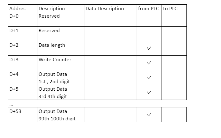
| Data address | Enter the start address (D) of the data area. |
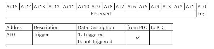
| Control address | Enter the start address (A) of the control area. |
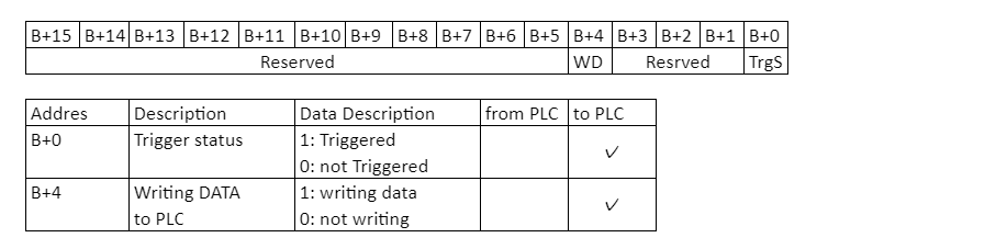
| Status address | Enter the start address (B) of the status area. |
| Interval | Enter the PLC interval to use. |
| Enable trigger by PLC | Check here to control trigger by PLC. |
Memory map
Data area (D)
For Mitsubishi PLC, it is D (data register).
Control area (A)
For Mitsubishi PLC, it is Y (output relay).
Status area (B)
For Mitsubishi PLC, it is X (input relay).
RS-232C
Settings for connecting the scanner with the RS-232C interface.
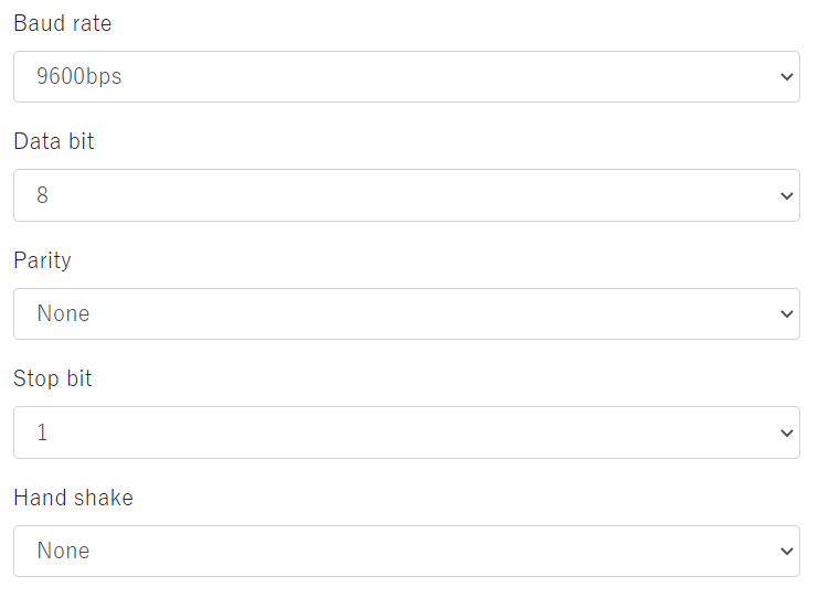
| Baud rate (transfer speed) | The transmitted speed of bits from the scanner to the host and from the host to the scanner. Select to be the same speed as the host. |
|---|---|
| Data bit | Set the data bit. |
| Parity | Add parity bit to each character so that the total number of data bit 1 including parity bit becomes odd for odd parity and even for even parity. |
| Stop bit | Set stop bit. |
| Hand shake | Select from None / ACK / NAK on the Web. For other settings, refer to FA-5201 User's manual. |
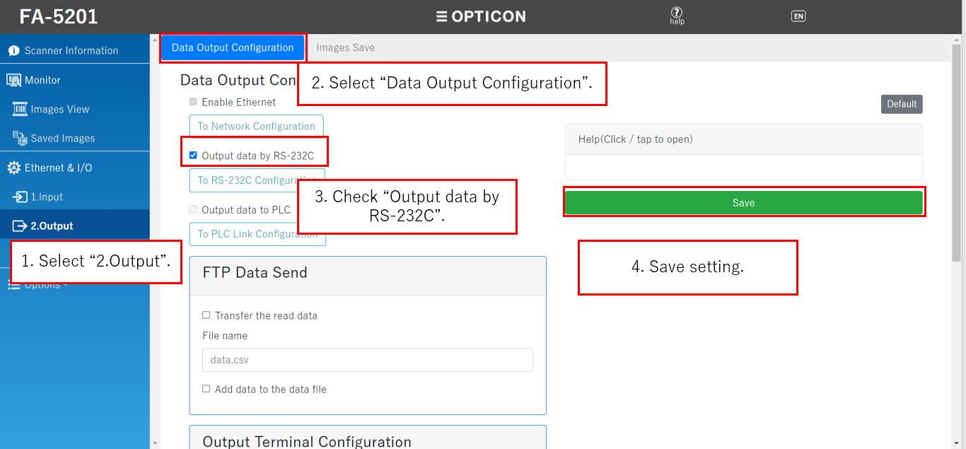
To send scan data with RS-232C, select "Data Output Configuration" in the left side menu "2.Output", and put a check to "Output data by RS-232C", then click "Save".
FTP Connect
Setting to connect the scanner to the FTP server.
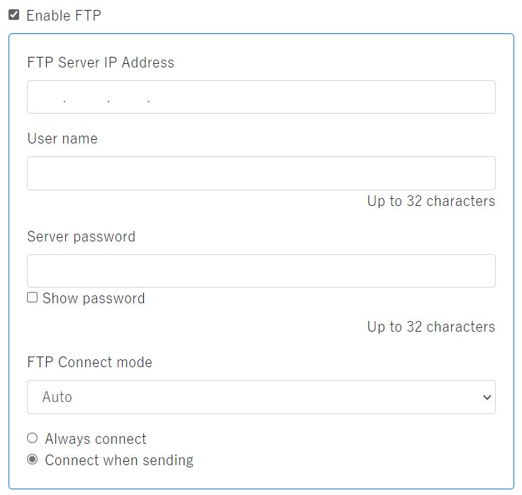
| Enable FTP | Check here to use FTP communication with FA-5201. |
|---|---|
| Server address | Enter the FTP server address to use. |
| User name | Enter the user name to use in FTP communication. |
| Password | Enter the password to use in FTP communication. Check the "Display password" check box to visualized the password. * Characters that can be used in the user name and password: Up to 32 single-byte alphanumeric characters and single-byte symbols. |
| FTP Communication mode |
|
| Always connected | The scanner and server become always connect. |
| Connect when sending | The scanner and server start a connection when sending and disconnect when sending or reception is completed. |
Change Directly
When transferring and saving the images by FTP, the directory to be transferred can be selected from your home directly.
The "home directory" is the storage location specified in the FTP server to be used.
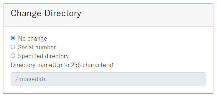
| No change | Save in home directory. |
|---|---|
| Serial number | Save in the folder that has the same name as the scanner's serial number in the home direcory. |
| Specified directory | Save in a folder that has the same name as the character string written in the "Directory name" in the home directory. |
Note: There are limitations to the symbols that can be used for directories depending on the OS.
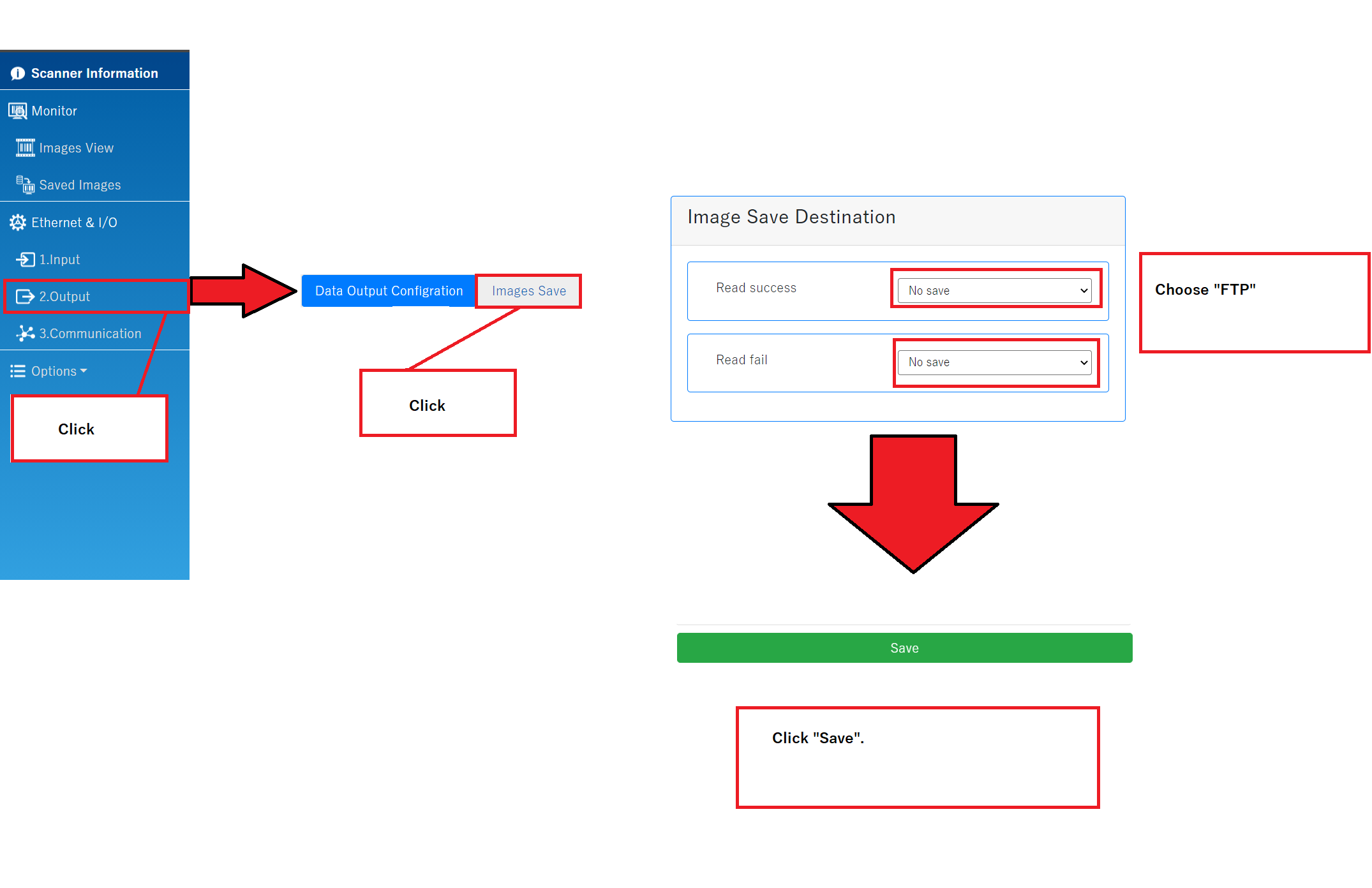
To save the images using FTP communication, after setting here, go to "Images Save" in the left side menu "2.Output" to set.
SNTP
Set the current time to the scanner by connecting to the SNTP server.
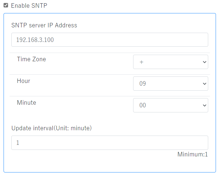
| Enable SNTP | Check here to connect the FA-5201 to the SNTP server. |
|---|---|
| SNTP server address | Enter the IP address of the SNTP server to use. |
| Time zone | Set the time zone according to the country where the scanner is used. |
| Update cycle | Enter the cycle to connect to the SNTP server and update the current time. |
Following are the typical time zone.
| Time zone | Place |
|---|---|
| -8:00 | Pacific Standard Time (USA, Canada) |
| -6:00 | Central America (USA, Canada), Central America |
| -5:00 | Eastern Standard Time (USA, Canada) |
| -4:00 | Atlantic Standard Time (Canada) |
| -3:00 | Brasilia |
| -2:00 | Central Atlantic |
| -0:00 | London, Lisbon, Coordinated Universal Time |
| +1:00 | Berlin, Rome, Brussels, Paris Stockholm, Wein |
| +2:00 | Athens, Jerusalem, Cairo |
| +3:00 | Kuwait |
| +4:00 | Moscow |
| +5:30 | New Delhi |
| +7:00 | Bangkok |
| +8:00 | Beijing, Hong Kong, Kuala Lumpur, Singapore, Taipei |
| +9:00 | Japan, Seoul |
| +10:00 | Canberra, Sydney |